Very often on Support requests we don’t know much about the environemnt mAirlist is used in and how it was Setup. So I started to do little drawings of common use cases. I would like to start a discussion here, what I might miss and what you think I should create as a schematical drawing.
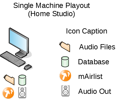
My first try is just focused on the Software and its various parts that can be spreaded over several Computers/Servers in larger environments.
Later we can also do the same for typical audio routings
1 Like
Fine! Next you can supply an icon for a NAS (or else) hosting the DB-symbol.
And maybe you want to add an icon for a hardware interface.
Completed regards
TSD
Well I was working on that already, while you are writing it.
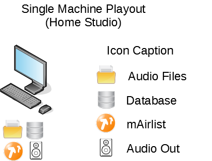
Reworked Home Studio
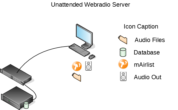
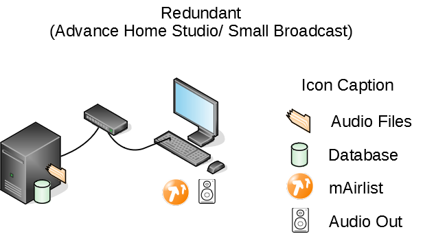
And the more Advance Studio, I call it redundant, because ususally you run a RAID on a NAS for redundancy.
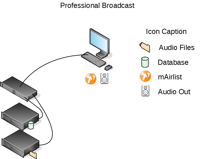
And another one, even more advanced.
The next one is the one that I run as our Masterserver. The Diagram shows independet Hardware components but you can also replace any hardware icon with a virtualized apliance, as I have done.
In my case mAirlist is running a Playout instance and the mAirlist DB-Server, because I have the audio files there and it is a virtual machine I can’t get any higher redundancy seperating the DB-Server or the audio files to another virtual machine. I just seperated the PostgreSQL Backend to another Container, becasue it is way easier to maintain it as a Linux Container.